The Shaving Cadre

Welcome to The Shaving Cadre, a forum dedicated to gentlemanly discourse about wet shaving and other topics of common interests. Membership is always free so register today and join in the fun

Gibbs Adjustables and their offspring

Adjuster plate update

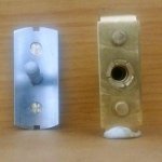
From L-R: Standard plate - Version 1 - Version 2 - Version 3. (With 4 different views of them)

@smurfups77 - I was actually busy fiddling with version 3 when I saw your notification come through, but I decided to wait until I tested it in my other Gibbs razors and also take some pics.

I believed (correctly so) that the main issue with version 1 that it was too thin. The standard plate is 1.5mm in thickness and I didn't have any brass in that size, so I used the next size up which is 2mm (Version 2 in the picture). I didn't finish it off because when I had it in the razor I saw that the the gap is way too big.

The answer was to get a piece of 1,5mm brass plate, which I managed to get last week.

Version 3 is the correct thickness. I haven't shaved with it yet, but everything looks right.
The making of the plate is pretty easy, albeit lengthy, but getting the height of the posts is finicky. It also turns out that its not a "one-size-fits-all" part, it doesn't necessarily work with the other top-caps.

Two of the top-caps that I have, have a recess in the top and the third has none.
On the second top-cap with the recess, its very close but would still need a bit of fitting.
On the top-cap without the recess, it needs a fair bit of fitting

Where to from here - I'm not really sure. I have some ideas floating around in my head but they would require the standard Gibbs top-cap to be modified with two very shallow 5mm blind holes to accommodate the posts. It would mean that the height of the posts is no longer critical but I'm not really about modifying the original parts.

I'm also happy to listen to suggestions/ideas - so fire away

Version 3.jpg
 
It's a tricky problem for sure if the caps are varying so widely.

Just looking at mine, I see another issue. The tab also aligns the top cap, so even if the blade is aligned with the current system, you'd still have to fiddle with the cap alignment, unless I'm missing something.

If you ever made some more of those punches, I'd probably be more interested in that as a customer, FWIW. I still haven't come up with a reliable way to punch the blades. It's been pretty hit or miss.
 
Just looking at mine, I see another issue. The tab also aligns the top cap, so even if the blade is aligned with the current system, you'd still have to fiddle with the cap alignment, unless I'm missing something.
It self aligns because you have some curvature under the top-cap and a parallel adjustment plate, so it naturally falls into place.
It was one of my initial concerns and the reason for me initially thinking of the small blind holes.
 
It self aligns because you have some curvature under the top-cap and a parallel adjustment plate, so it naturally falls into place.
It was one of my initial concerns and the reason for me initially thinking of the small blind holes.

Ah, yes of course! In that case would a bar style guide work? I have a groovless cap, but it does look like there is a fair amount of free space under the peak of the cap. I imagine it's harder to make though.
 
Question: do the posts have to be as high as they are? Could they be just a little higher than thickness of a blade so that they act more as guides? That might help with the variability on the top cap.

Also - I'm right behind @HMan in line if you ever decide to sell a punch tool.
 
Ah, yes of course! In that case would a bar style guide work? I have a groovless cap, but it does look like there is a fair amount of free space under the peak of the cap. I imagine it's harder to make though.

If by a "bar style guide" I think that you mean similar to a Personna but longer. My initial plan was just to really copy the Personna. I actually tried the adjuster plate in my Gibbs but its posts are too high and the Personna top cap has slots to cater for them. It meant re-indexing work and that could cause other alignment issues.

Question: do the posts have to be as high as they are? Could they be just a little higher than thickness of a blade so that they act more as guides? That might help with the variability on the top cap.

Also - I'm right behind @HMan in line if you ever decide to sell a punch tool.

The posts have to have some height because when you tighten the top-cap down the blade curves (and raises itself in the middle). I wanted it as close to the top cap as possible to ensure the the blade doesn't have any chance of slipping off. I'm not sure if they need to be as high as the underneath of the top cap but that is certainly worth a look.

When you guys are talking a punch tool, I hope that are you meaning the simple one?
 
If by a "bar style guide" I think that you mean similar to a Personna but longer. My initial plan was just to really copy the Personna. I actually tried the adjuster plate in my Gibbs but its posts are too high and the Personna top cap has slots to cater for them. It meant re-indexing work and that could cause other alignment issues.

Yes, I was thinking something similar to the Precision, but thanks to Google, I just saw the how deep the slots in the head are, and see what it likely has the same issue. :(
 
When I bought my first Gibbs, I read about the punch and the cutting of the tabs but neither were a satisfactory solution for me. The first jig that I made was more of a template than a jig and I used a Dremel to cut the slots. It worked fine but you needed to be careful using it because the Dremel, besides cutting the blades could also cut the jig.

I then made one on a milling machine, where I slit a piece of metal and used a pin to punch the notch. It works well but not everyone has access to a milling machine and I still wanted to design something that could be made with some basic tools.

This is what I came up with. It also served as a proof of concept for what I ultimately had in mind.
(It has been posted on another English forum and was translated and posted on the French forum)


You are going to need:

A piece of sandpaper

A 3mm Drill bit that you are going to sacrifice. The 3mm drill shown here has been sharpened a lot. If you have a piece of round 3mm tool steel, which of course a drill is - use that.

2 x nuts and bolts

A drill to match the two bolts (I used a 5mm here)

A strip of aluminium from a beverage can

Two pieces of metal

Marking pen or scribe (Something to mark the aluminium can)

Scissors or trimming knife/box cutter
(These scissors are too big as you will see later)

Hand drill (although I have a milling machine, I wanted to make this out of basic tools)

Not Shown:
Trimming knife / Box cutter
The two nuts and bolts
Scribe

Optional:
A Clamp (I didn't use one because again I wanted to use basic tools)
Drill the three holes.

The two outer ones to match the nuts and bolts that you have. They must be wide enough apart to clear a blade so anything more than about 30mm will work. The 3mm hole somewhere close to the middle

If you have a clamp use it here to clamp the two pieces of metal together before you drill them. I didn't and my two pieces don't line up exactly. If you look carefully at the top of the image you can see this.

I then sandpapered the top end of the 3mm drill bit so that it was flat and snapped it off. Effectively it's going to work like a scissors. If you have access to a Dremel (or similar) rather cut off the excess of the 3mm drill bit. The fact that I snapped it created a problem which I mention later.

While I was doing sandpapering, I also cleaned to the two pieces of metal.

You want to end up with something like the two pieces in the bottom half of the image. The countersinking is optional. I counter sunk the two outer holes because that matched the two bolts that I was using.

Up to now the only mistake that you can make is that the two outer holes are not far enough away from the middle hole and that they interfere with the blade edges when you insert the blade.
The second part of the jig
This is what determines how accurately the notch is done so you do need to be careful

Cut a suitable size strip from the aluminium can.

A - Mark and punch the two outer holes. I used a paper hole punch to do punch these holes.

Assemble the jig, sandwiching the piece of aluminium strip between the two steel plates.

B - Punch the middle hole using the flattened (snapped) drill bit - At this point I found out that my drill was slightly bent from breaking it. It worked fine but I had to pull it out with a pair of pliers - so I suggest that you cut it with a Dremel if you can.

I wasn't going to snap another drill bit so I used the pin that I already had and punched the rest of the small holes in the image.

C- If you have an old Gibbs blade use that, otherwise you are going to have to do some careful measuring. I took a blade that I already punched and marked the aluminium out using that.

D - The Marking pen works fine but I found that scribing it was better.

E - Cut where you need to. Also cut off the excess so that there is no aluminium sticking out. You want to end up with the aluminium similar to this. I have no aluminium that touches the sharp edges of the blade.

This is going to determine both the depth and the centering of the notch. It was at this point that I found that the scissors were way too big, so I ended up using the ones on my Leatherman. The aluminium strip is soft and cuts easily.

On the second "notcher" I used a box cutter/trimming knife to cut the aluminium and frankly this is the best thing to use.

This part needs to be accurate as it is what does the alignment. The great part is that if you make a mistake, just cut another strip from the can and start again. On the second notcher the can that I got was not thick enough so I just used two strips.

Now it’s time to re-assemble everything.
When you do, put the pin so the aluminium lines up and then tighten everything up
To use:
Slide the blade into the jig.

Lay the jig down flat.

Insert the pin and give it a smart tap. Repeat for the other side. I used the screwdriver in the image to tap it.

The top of the image shows one side done and the blade inserted before doing the other side.

Does it work - absolutely perfectly, all the time every time. Its also fairly quick to use.

See the bottom part of the image. The blade is perfectly lined up in my Gibbs.


I have since milled the edges so that the corners are all square just to have it neat and tidy, but is not necessary.


This is where I wanted to end up. I saw that my idea worked fine so all I really did was build a pin/spring arrangement on top.
I also wanted to be able to use it in a reloading press, hence the thread and the little piece on the left hand side. Using it in a reloading press is extremely fast although I suspect that it won't get much use this way.

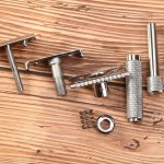
This was done using a lathe and a milling machine. Left part of the pic shows the components (I forgot to put the white handle in the pic) and the other side shows it in use. Insert blade, smack the white handle, turn blade around and smack the white handle again.

I bought, the bolt and the two pins. I have no idea where the spring came from, I have a packet of springs that have come out of "things" over the years and its was among them. It needs to be fairly strong.
I built it over two evenings.

Is it Overkill - absolutely
Was it fun to build - absolutely.
Is it Quick to use - absolutely


Any questions, I will do my best to answer - otherwise Happy Building Gents!!
@Clouds I was thinking something like Notcher 2, since it seems the easiest to use, but really any sturdy jig that lets me consistently and easily punch holes in blades would be amazing.
 
That looks good Clouds I look forward to hearing about the shave with the newest version. I would love to have either a plate like this or a jig to make the blades fit perfectly. Keep up the good work.
Happy shaves
SMURF
 
Gibbs "Standard Blade" R&D continues

Before I start on yesterdays R&D, this needs to be said. My version 3 works perfectly provided that you assemble everything in the right order. Take the blade, lay it over the posts, drop the top cap on top, finger clamp it together, wiggle around a bit to center and then insert and tighten the twist knob. I've tested it probably 50/60 times and it works flawlessly. If you don't do the wiggling bit you may end up with the top cap not been aligned and the blade not been clamped along its full length. The alignment of the top cap works great bit is not foolproof so IMHO not a 100% working solution.

Onto yesterdays Gibbs R&D:

Firstly I made the shallow posts. They work like my others provided you fit it together in the above order.

I then decided that I was going to drill a top cap (I need to get past the drilled top cap idea) I had one of those Gibbs that doesn't come apart. Its top cap is one of those that does not have the recess in it so also a better candidate because of the slight extra thickness. I drilled the two 1mm deep blind holes, made a new adjuster plate with higher posts. It works exactly as I expect it should. Those two shallow holes make a huge difference.

This is not the "drop in" solution that I am looking for but at this point it is the best one out there.

I did some overzealous filing on the side tabs when I fitted the adjuster plate to the bottom plate, so it's not quite where I want it. (This was at 11pm last night so there might have also been some tiredness) so I'll be remaking another one in the next few days. I need to get to my day job today so that I can afford the toys..:cry:

This pic shows the underneath of drilled top cap plus the corresponding adjuster plate.

Gibbs_AP_09.jpg
The next pic shows the top view of the same top cap, version 4 of the adjuster plate and version 3 of the adjuster plate

Gibbs_AP_10.jpg
 
Once the Gibbs replica comes out I will be looking forward to @Clouds review for sure. I’ll also be wondering if the replica’s adjuster plate/cap will be useable in the Gibbs or if Claudio’s handle/extension will be swapable in the replica. I hope shipping to South Africa isn’t too long.
 
Claudio your dedication to the Gibbs is inspiring to say the least and props to you my friend! I also 2nd a blade hole punch that is accurate and easy to use as I have not found one yet so I've resorted to just cutting the blades. That goes fast but trying to align the blade once I tighten the top cap down is certainly challenging especially with my diminishing eyesight. LOL So I'm all in if you come up with one we can purchase. One thing that appeals to me about the Taiga when I used the pass around. Just pop a blade in and go!

Thanks for all you do! (y) 🙂
 
(y)
The perfect Personna-lization !
(the word game works better in french: "personnalisation" seems "customization")
 
@AJSharp - There are guys far more qualified to give an opinion on the Heritage. I'll give my thoughts on it but in reality I'm just hoping that one of the first batch has my name on it.....

@Dragonsbeard - Thanks for the words. Its more about keeping my grey cells working.
Some good news on the punch. There is one "hopefully" leaving tomorrow (that is if our Post Office will accept international post!!). I think that its easy to use, lets see what he says. Plexus is also working on something.

@Plexus - Thanks. Its something you and I have spoken about. Its going to be interesting to see what the forum that you frequent say about it. Its plagued you guys for longer than it has plagued us.
 
Gibbs "Standard Blade" R&D continues

Before I start on yesterdays R&D, this needs to be said. My version 3 works perfectly provided that you assemble everything in the right order. Take the blade, lay it over the posts, drop the top cap on top, finger clamp it together, wiggle around a bit to center and then insert and tighten the twist knob. I've tested it probably 50/60 times and it works flawlessly. If you don't do the wiggling bit you may end up with the top cap not been aligned and the blade not been clamped along its full length. The alignment of the top cap works great bit is not foolproof so IMHO not a 100% working solution.

Onto yesterdays Gibbs R&D:

Firstly I made the shallow posts. They work like my others provided you fit it together in the above order.

I then decided that I was going to drill a top cap (I need to get past the drilled top cap idea) I had one of those Gibbs that doesn't come apart. Its top cap is one of those that does not have the recess in it so also a better candidate because of the slight extra thickness. I drilled the two 1mm deep blind holes, made a new adjuster plate with higher posts. It works exactly as I expect it should. Those two shallow holes make a huge difference.

This is not the "drop in" solution that I am looking for but at this point it is the best one out there.

I did some overzealous filing on the side tabs when I fitted the adjuster plate to the bottom plate, so it's not quite where I want it. (This was at 11pm last night so there might have also been some tiredness) so I'll be remaking another one in the next few days. I need to get to my day job today so that I can afford the toys..:cry:

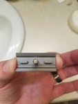
This pic shows the underneath of drilled top cap plus the corresponding adjuster plate.

The next pic shows the top view of the same top cap, version 4 of the adjuster plate and version 3 of the adjuster plate
Great work on that one. That is the type of top cap iij have on mine. I thought about it and looked at mine a lot last night. Just a thought but could you use these type post.20200531_171237.jpg
They would line up with the end cut outs on the top cap. They would be more narrow and you could make them taller than the round ones I think without having to alter the top cap. I know you are smarter than I am about this stuff but though I would throw it out there. Also is there is the same amount of place between the adjuster plate and top cap on all the ones that use this cap then you could make one kind for this style cap and one for the other. I may have one more idea but will have to think about it some more. Keep up the good work.
Happy shaves
SMURF
 
@smurfups77
Actually the ridges were my original plan. It presented me with my equipment and machining skills with a few problems, so that's why I didn't go that route.
Ideally I thought that it would be machined in two pieces without taking either out of the vice until they were complete - the top piece with the integral ridges and then the "stem". That process is ideally done on a CNC.

Its a good idea and I'll probably give it a try. If I commissioned the work out to a CNC shop this is most likely the route that I would go.

I've done a bit on the new plate. I'm fitting it in as I can at the moment.

Keep the ideas coming gents.
 
Back
Top